|
|
|
|
|
|
|
|
|
|
|
Free Space Optical Communication Systems |
are used for transmitting of analog and digital signals with speed up to 5.6 Gbps in infrared bands |
|
|
|
Solutions for: |
|
Internet Service Providers. Video-Multimedia. Military communications . |
|
National Telecommunications . Multiple building connections . Universities . |
|
Airoports . Airplane - geostationary satellite laser communication. |
|
Data rates of 5.6 Gbps are being demonstrated over laser communication link between |
|
of low earth orbit TerraSAR-X and NFIRE satellites. |
|
Advantages: |
|
No licensing required,. Full duplex at high data rates. Secure data transmission. |
|
Easy to relocate links. No need to dig up roads for cables. |
|
No cross-talk or electromagnetic interference. Immune to EMI and RFI. |
|
Indoor or outdoor installation. Bit error rate less than 10E-9. |
|
Immediate installation and connectivity. |
|
What is better? |
|
- Fibre optical communication systems ( FO ) |
|
- Air ( space) optical communication systems ( AO ) |
|
- Radio frequency communication systems ( RF ) |
Bit Rates: |
RF: 10-150 Mbps / channel. |
FO: 10 Mbps – 80 Gbps ( N x Tbps if we use Dense-Wavelength-Division-Multiplexing). |
AO: 10 Mbps – 5.6 Gbps / channel. |
|
Air laser communication systems - decision of « Last mile problem » Advantages: No licensing required, secure data transmission, no need to dig up roads for cables. |
|
Is it possible laser communication from ground to space ? What is influence of atmosphere at the directions ground - space or space - ground ? |
| . |
|
Laser communication program of ESA |
|
For several years ESA developed laser communication
program for communication between low earth orbital (LEO) and geostationary (GEO) satellites.
|


The Optical ground station was constructed at Teide observatory, Tenerife,
Canary Islands for laser communication experiments from ground to geostationary
(GEO) satellites. The SPOT-4 LEO satellite was launched
in 1998 with laser
communication terminal aboard for communication experiments with GEO
satellite. In 2000 year we performed calculation and made an opinion, that similar laser communication experiments with GEO satellite possible using ordinary astronomical telescopes of our observatory. ESA
telecommunication satellite ARTEMIS was launched on 12 July 2001. He has RF channels and SILEX device
(Semiconductor Laser Inter Satellite Link Experiment) that works at 2 Mbps and 50
Mbps rates. |


After
its launch ARTEMIS was placed onto degraded orbit due to a multifunctions in Ariane 5 upper
stage. After the correction of the orbit ARTEMIS placed to “parking”
circular orbit (h=31000km). Experiments with optical communication system SILEX
at “parking” orbit ware successfuly performed in November 2001 . After that ARTEMIS was “spirally” moved to
the nominal geostationary orbit
using the satellite’s electrical
ion-propulsion system (www.esa.int). In June 2002
specialists of ESA visited our observatory. After matching of calculations and discussing during
visit we showed, that the same experiments of receiving-transmitting the information by laser communication
channel and investigation of atmosphere influence at the propagation of laser
beam between geostationary satellite and the ground station can be performed
using common astronomical telescopes and semiconductor laser transmitting system. |
|

It is clear now, that it is possible compare the differences in atmosphere propagation of laser beam between Atlantic (ESA OGS) region and continental (MAO) region. Also it will be possible to investigate the amplitudes and phases of optical pulsed signals in different atmosphere conditions; investigate the fluorescence and scattering on aerosols.
MAO has agreement of ARTEMIS managers about our
participation in optical communication experiments with ARTEMIS satellite.
National Space Agency of Ukraine (NSAU) supported this participation. |

In January 31, 2003 geostationary
satellite ARTEMIS ESA with laser terminal aboard was put into the planed orbit
point of geostationary orbit above 21.5 E. - Nowadays sessions of
transmitting of information by laser channel from low-orbital SPOT-4 to ARTEMIS
satellite with next retranslation of the data by radio channel to the ground
station are performing regularly. Laser communication experiments between
ARTEMIS satellite and optical ground station (OGS) ESA at Canary Islands are
performing also. Japanese Space Agency also participates in ESA laser communication program. NASDA prepared the LEO satellite OCIETS with LUCE laser communication terminal aboard for transmitting of information onto ARTEMIS satellite. In September 2003 LUCE terminal was tested at ESA OGS and successfully performed laser communication sessions with ARTEMIS satellite. These experiments proved our calculations and our technical solutions of preparing laser communication experiments from ground to space using semiconductor lasers. (www.nasda.gov.jp) |


The low-orbital satellite OCIETS with LUCE terminl of Japanese Space Agency was launched in August 2005 by Ukrainian rocket " Dnipro ". |
|
ESA and NASA plan the experiments of laser communication from Moon and Mars orbits. SMART-1 satellite near the Moon. |

|
|
Our preparation to optical communicational experiments with geostationary satellite |
|
MAO performs the preparation to test experiments with ARTEMIS satellite using two telescopes: 0.7 m ordinary astronomical telescope and 1m Laser Ranging Station (LRS). The purpose of the experiments with ground stations is to compare differences in atmosphere propagation of laser beams between Atlantic and continental regions, investigate the amplitudes, phases of optical pulsed signals in different atmosphere conditions, perform wave front measurements, scattering on aerosols and small clouds, investigate fluorescence in upper atmosphere. |
|
CW laser module |


CW laser test experiments A scattering of laser beam on aerosols [watch the movie] |
|
|
|
Realisation of laser communication experiments with ARTEMIS satellite Realisation of laser communication experiments is performed under the ESA contract "Assessment of Space to Ground Optical Link by Space Diversity". Equipment for laser communication experiments was developed for Cassegrain focus of AZT-2 telescope. Telecommunication satellite ARTEMIS was launched on 12 July 2001. It was at the geostationary orbit point (21E) at the end of January 2003. Due to a multyfuntions in Ariane 5 upper stage ARTEMIS has inclination of the orbit (Now > +/- 7 deg). Spacial correction system of moving of the telescope was developted.
The tracking system works in micro-step regime with a computer step of correction = 0.003 arcsec per second of time and a maximum speed of correction up to 4.6 arcsec per second of time. The step regulation is possible directly from block of correction situated near the telescope. Also it is possible to correct the moving of the telescope using the computer RS-485 interface in remote mode. The pointing on the satellite is performed by CMOS camera (2000x3000 pix) with wide field of view. Another cooled small CCD camera (582x752 pix) with narrow field of view is used for tracking purposes. |
|
|
|
|
|
For testing of tracking the calculations of middle photometric positions and fluctuations on X, Y coordinates of images of ARTEMIS were performed. The results of calculations of satellite images with an exposure of 5 second show that standard root mean square deviation along X coordinate is 0.65 arcsec and along Y coordinate is 0.4 arcsec during 3 minutes of time for the set of images. |
|
FIRST LASER EXPERIMENTS WITH ARTEMIS SATELLITE
Our work has been performed with an amount of support from The European Space Research and Technology Centre ESTEC and REDU SPACE Services station. First laser experiments with ARTEMIS were performed on 9th and 10th of November 2008. We had 3 sessions for 6 minutes of beacon scanning each night. We received the beacon signal during all the scanning time. First maximum beacon signal was received 15 seconds after the beacon was turned on. The second maximum was seen 19 seconds after. We sent laser beam to the ARTEMIS direction during all last session.
ARTEMIS laser beacon observations A short movie featuring ARTEMIS laser beacon observations. [watch the movie]
During the sessions of 26 October 2011 (19:00 UTC, 20:00 UTC, 21:00 UTC) the sky was partly clouded. Weather conditions were unstable and we recorded these sessions automatically. We were browsing the images of those sessions and found that the beacon was visible through clouds. By this means, it is possible to observe the beacon through the clouds and, accordingly, laser communication link through thin clouds can also be established. |
|


 Block of correction of moving of AZT-2 telescope for tracking of the satellite
 Common view of the technology platform with main subsystems in Cassegrain focus of the 0.7m telescope
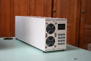
  Electronic block for thermoelectric cooling of laser diode
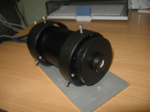
 Laser module with thermoelectric stabilisation of laser diode. Wavelength is 850 nm.
  CMOS-camera testing
  ARTEMIS and a star track. CCD camera and 1-second exposure
  Tracking of ARTEMIS. CCD camera and 5-second exposure.
 Laser beam via clouds